Reshaping Agricultural Field Terrain
📄📄📄
I still think it's a useful idea, and I hope someone has use for parts (or all) of it.
📄📄📄
ABSTRACT
A system and method for preserving topsoil when reshaping agricultural field terrain. An iterative sequence consisting of multiple soil inversion, excavation, and deposition events are used to raise or low different parts of the field according to a predefined design, at the same time preserving topsoil at its original location as the topmost soil layer. Multiple machines utilizing computerized machine control are used according to a prescription that is calculated from data sources relating to existing and design field terrain, machine soil inversion capabilities, and topsoil depth. The result is that the terrain surface is altered to match the desired design, while the critical vertical distribution of fertile soil layers is neither disrupted nor destroyed. Machine control maps to facilitate other relevant spatial tasks such as rolling, irrigating, ripping, or applying soil ameliorants may also be produced.
TITLE
A system and method for reshaping agricultural field terrain.
TECHNICAL FIELD
The present invention relates generally to the field of agricultural earthmoving. Reshaping the terrain of farm fields is performed to improve water surface-flow and infiltration patterns, and to improve machine efficiency and field trafficability. In common scenarios machines such as bulldozers and tractor-pulled scraper pans are used to excavate soil from locations that need be lowered (cut areas) and to deposit it in locations that need to be raised (fill areas) as per the requirements of a predetermined terrain design.
BACKGROUND OF THE INVENTION
The following references to and descriptions of prior proposals or products are not intended to be, and are not to be construed as, statements or admissions of common general knowledge in the art. In particular, the following prior art discussion does not relate to what is commonly or well known by the person skilled in the art, but assists in the understanding of the inventive step of the present invention of which the identification of pertinent prior art proposals is but one part.
Agricultural earthmoving
Agricultural earthmoving machinery commonly uses computerized machine control and high precision GPS to excavate and deposit soil. Implements (such as dozer blades) can automatically seek target heights for each location in a field. United States Patent US6880643B1 discloses such a system. The human machine interface (HMI) can show the operator where soil needs to be excavated, and where it needs to be deposited. The machine control system requires a digital spatial prescription. This prescription usually contains various relevant layers, including design elevations (post-earthmoving) for each location in the field. In most cases the system will also contain a corresponding layer for the existing field surface (pre-earthmoving). An often-included derivative of these two layers is the "Cut/Fill" layer which shows the operator where and how much soil must be excavated, and where and how much must be deposited, in order to create the new field surface. Australian Patent AU2008207380B2 discloses certain methods for creating such field designs. Some systems keep track of activities as they occur. For instance, excavation and deposition events can be recorded in real time, one outcome of which is the display of a layer that represents the current elevation status of all locations within the field as work progresses.
Earthmoving machinery acts firstly on the topmost soil layer. This top layer is often the most agriculturally productive soil, containing attributes conducive to good crop growth. In parts of the field that need to be lowered the rich topsoil is excavated and less fertile subsoils are exposed. The high value soil will then be deposited elsewhere, normally in areas that already have an existing topsoil layer present. When filling an area, highly productive soil layers can be covered over by less productive soil from elsewhere in the field. The common result of agricultural earthmoving is that, while the final terrain surface is improved, the critical vertical distribution of fertile soil layers is disrupted or destroyed. Affected areas can take years of rehabilitation to return to former fertility, or may never recover.
In certain situations, topsoil is removed and stockpiled. The now-exposed subsoil is then shaped to match the desired three-dimensional design, before the stockpiled topsoil is reapplied evenly to the new field surface. This is an expensive and time-consuming procedure as it involves hauling large amounts of soil long distances to and from stockpile locations. The stockpiles themselves can be problematic, as room for them must be found in areas where they do not impede the earthmoving operation. Generally, this practice is limited to only the highest value lands and applications. United States Patent US20160275218A1 discloses a method utilizing soil modelling as well as topsoil stockpiling to reduce topsoil disruption.
Soil inversion
Certain methods of tillage fully or partially invert upper soil layers for various reasons. In some systems this is done to bury weeds and crop residue deep in the soil, where they can decompose and provide nutrients for the next crop. In others it is used to break up and aerate the seedbed. It has also been used to mix or replace low quality surface layers with desirable subsoils. Square ploughs, mouldboard ploughs, and certain disc ploughs are all examples of tillage equipment designed to invert the top layer of soil. Such implements are well known art but previously have only been used in relation to earthmoving as tools to loosen soil layers before excavation occurs. For an example of this see Japanese Patent JP4898131B2.
Variable depth tillage
Variable depth tillage is a type of soil cultivation practice that uses machine control to continuously adjust the implement depth. It allows operators to adjust depth of tillage based on specific soil conditions, management goals, or other needs for each location in the field. This can reduce soil compaction, improve soil structure, and optimize seed placement and root growth. An example of such a system is disclosed in Chinese Patent CN108377686B.
SUMMARY OF THE INVENTION
The system and method disclosed provide a new, efficient, and practical mechanism for preserving valuable topsoil layers during agricultural earthmoving operations.
The process of moving soil from one location in a field to another is termed here 'surface modification', and the processes of re-ordering soil layers at a location in the field is termed 'soil inversion'.
The invention solves the problem of topsoil disturbance in agricultural earthmoving by combining known art and techniques from the fields of agricultural earthmoving, soil inversion, and variable depth tillage in a novel and non-obvious way.
Using embodiments of the method, it is possible to alter any field's surface, creating any terrain shape, with indefinite elevation changes and spatially complex patterns, while retaining the original topsoil layer as the topmost soil horizon. The existing fertility of the soil in a field is preserved despite the highly disruptive process of field terrain reconfiguration.
Facilitating surface modification and soil inversion operations requires the creation of a plurality of prescription maps ordered according to a specific sequence of operations. These maps describe precise elevation targets for machinery used to facilitate both surface modification and soil inversion at each location in the field. As the operations they control must be performed in correct sequence, these prescription maps must also be used in the correct sequence. They are created by combining location specific values for variables including existing elevation, design elevation, maximum vertical inversion width, and topsoil vertical width. Output as digital control maps allows automation of the operations of machines that are both suitable for the specific surface modification and soil inversion requirements and also equipped with appropriate machine control systems.
BRIEF DESCRIPTION OF THE DRAWINGS
Figure 0 illustrates progressive altering a field's terrain using an embodiment of the invention described herein whereby soil is excavated from certain areas and deposited in another while at the same time the inversion of soil layers preserves the topsoil integrity of the field.
Figure 1 is a left to right sequence of a soil profile from areas of both of excavation (110) and deposition (160), illustrating the progressive effect of a series of soil inversion and surface modification iterations on the soil surface elevation, and its vertical profile.
Figure 2 is a flowchart showing the order of operations and calculations for an embodiment of the method for mechanically excavating soil from a field or field region without removing the topmost layer.
Figure 3 is a flowchart showing the order of operations and calculations for an embodiment of the method for mechanically depositing soil onto a field or field region without permanently burying the topmost layer.
Figure 4 is a flowchart showing one embodiment of the method for creating a set of sequential plans of soil inversion and surface modification operations suitable for use by machine operators.
Figure 5 is a flowchart showing another embodiment of the method for creating a set of sequential plans of soil inversion and surface modification operations suitable for use by machine operators.
Figure 6 shows two different progressions, each consisting of two iterations, whereby the same mounded surface is flattened using the method of the invention, but where the amounts of soil excavated in each iteration differ.
DETAILED DESCRIPTION OF EMBODIMENTS
Well known conversions exist between elevations, heights, depths, vertical width of layers, and other measurements and terms used to describe vertical positions, ranges, and distances in this description. For instance, a soil layer may have a vertical width of 10cm. It may exist at a depth of 20cm below the soil surface. The soil surface may have an elevation of 100m above mean sea level and 1m above a local benchmark. As such the soil layer may be described as existing between the depths of 20cm and 30cm below the surface, or between elevations of 70cm and 80cm above the local benchmark, or between 99.7m and 99.8m above mean sea level. The descriptions provided here do not consider such conversions or representations to be material to the mechanism or outcome of the invention being described.
Herein 'field' refers to a farm field or work region where terrain alteration for agricultural purposes is intended or in progress.
In the normal course of lowering the surface of part of a field, the topsoil layer [070] is the first soil to be excavated [120] and removed. In a preferred embodiment of the invention [110,210], prior to excavation, a process of soil inversion [025, 125] takes place, burying and preserving desirable topsoil [071] beneath a layer of less desirable subsoil [076]. This is done using an implement such as a mouldboard plough, square blade plough, disc plough, or other device capable of inverting soil layers [080]. The vertical width of inversion varies with location and is facilitated by an appropriate combination of machine control technology and an appropriate combination of vertical measurement technologies such as GPS, position sensors, distance sensors, or rotary sensors [082]. The vertical width of inversion at any point in the field is prescribed by a formula based on existing and design elevation maps, topsoil vertical width [118] (constant, instantaneously sensed, or mapped), and maximum implement inversion vertical width [135] (constant, or varying by location in field). After inversion [030, 125], the topsoil is now sequestered at depth and the area's elevation can be lowered in the normal way by excavating [035,120] surface soil. The vertical width of soil excavated is limited so that only inverted subsoil is removed. Once the buried topsoil layer is re-exposed at the surface, excavation at this location, for the current iteration, halts. If the area needs to be lowered further this procedure can be iterated [150] as many times as required. After an appropriate number of iterations, the area will reach the desired design elevation [111] and the topmost layer will remain the original topsoil layer present (although it may be upside down). Adjustments for expansion or compaction of exposed or inverted layers may be required.
A similar method is disclosed for dealing with fill areas [160,310]. In these locations, using standard industry practices, valuable topsoil [070] would be permanently buried by soil from other regions in the field. This can render the beneficial properties of this topsoil layer wholly or partially unavailable to the roots of sown crops or pasture. To avoid this an embodiment of the invention may complete the following procedure. During a surface modification operation, a layer of soil from elsewhere in the field [140] is deposited on top of the fill area of interest [041]. The vertical width of this deposition layer is carefully controlled such that, when summed with the underlying topsoil layer vertical width [118], the maximum inversion vertical width [135] capability of the inverting implement is not exceeded. The vertical width of the deposition layer must also be limited such that the final design elevation [111] of the location is not exceeded. Adjustments for expansion or compaction of deposits may be required. Once the new layer of soil [131] is deposited [140], a soil inversion [126] operation takes place from the surface down to an elevation equalling the bottom of the now buried topsoil layer. After this inversion [126], the deposited soil layer is below the topsoil, which is now back at the surface (although it may be upside down) [050]. This procedure can be iteratively repeated [150] as many times as necessary until the elevation of the fill area matches the final design elevation [111].
The method of this invention will only be applicable if the vertical width of topsoil present is less than the maximum vertical width of soil inversion possible [299]. The method of this invention remains applicable if the soil inversion mechanism available is not capable of perfect inversion. That is, the inversion mechanism may not be 100% successful, and a certain amount of mixing between upper and lower layers in the inverted soil column occurs. This may reduce the efficiency of the method, but will still normally result in beneficial outcomes.
Embodiments of this invention require earthmoving operations to proceed in stages, or as described here, "iterations" [150]. Each iteration involves a surface modification operation and one or more soil inversion operations. Each iteration progresses the current field terrain to a shape that is progressively less similar to the original field surface and more similar to the final design surface. The amount of terrain change possible in each iteration is limited by the maximum vertical width of soil that can be excavated or deposited in each iteration (W_currentcut [138] or W_currentfill [139]). This in turn is limited by the inversion capability (W_maxinvert) [135] of the utilized soil inversion machinery, the vertical width of topsoil (W_topsoil) [118], and the total vertical distance remaining to reach the design elevation (W_remainingcut [136] or W_remainingfill [137]). A preferred embodiment will not exceed W_currentcut or W_currentfill, although other embodiments may, as explained in the following paragraph.
In certain embodiments the user may determine minimum cut and fill vertical width tolerances. If the vertical width of soil to be excavated is less than a specifiable threshold value the user may choose not to invert the soil in this area. In this case the user may choose to sacrifice (by excavation) an amount of topsoil in order to avoid the inversion operation at that location. If the vertical width of soil deposited in a fill area is less than a specifiable threshold value the user may choose to not invert the soil in this area. The user may elect to allow topsoil to remain buried under an amount of soil in order to avoid the inversion operation at that location. These tolerances may relate only to the total cut and fill vertical widths at a location, or they may relate to the cut and fill vertical widths remaining after one or more method iterations.
It is not required that all locations in a field undergo the same number of iterations in order reach completion. Alternatively, another embodiment may express this same concept by assigning the same number of iterations to the whole field, while having certain parts of the field prescribe no surface modification or soil inversion events for one or more of these iterations.
Although at least one soil inversion operation is expected in at least one part of the field in each iteration, it is not required for all buried topsoil to be exposed at the end of each iteration. That is to say, it is not required that all cut and fill areas be inverted each iteration. Due to discrepancies in shape, size, and number of cut and fill areas in a field it may not be possible to exactly match the soil produced by excavations in one iteration with the total available fill volume in that same iteration. If the maximum amount of excavation permissible in an iteration fails to produce enough soil to raise a fill area to an elevation that maximizes the efficiency of the soil inversion operation, that inversion operation can be skipped until a future iteration. The opposite is also true. If the maximum amount of deposition volume available in an iteration is filled before all allowable soil is excavated, the next inversion of the excavation area can be delayed until a future iteration.
In different embodiments, the surface modification and soil inversion operations may be performed by the same machine in the same operation, by the same machine in separate operations, or by separate machines in separate operations. If the surface modification and soil inversion operations are performed by the same machine, that machine must be equipped with separate mechanical apparatus suitable for performing each operation.
Preferred embodiments of the invention contain logic residing within a computer program. In one embodiment the program may reside on a controller within the machinery performing the relevant field operations. The program may be integrated with machine control software within said controller, or may be an independent process within said controller. In another embodiment the program may reside in an office computer remote from the field. In another embodiment the program may be implemented as an online service.
A preferred embodiment begins with the acquisition of certain starting parameters. At minimum these are:
- Any two of the following three layers [420] (the third of which can always be calculated using a combination of the other two)
- A data source containing the existing surface elevations for every location within the field (Existing Surface Map).
- A data source containing the design surface elevations for every location within the field (Design Surface Map).
- A data source containing the excavation and deposition vertical widths for every location within the field (Cut/Fill Map).
- The maximum vertical width of soil inversion possible using the intended soil inversion technique in the field (W_maxinvert) [135].
- The vertical width of topsoil (W_topsoil) present [118].
In a preferred embodiment the maps are used to calculate a total required excavation vertical width (W_totalcut) [131], or total required deposition vertical width (W_totalfill) [132] at each location in the field.
Herein the W_topsoil [118] parameter is set by the user according to their specific purposes. The soil horizon delineated as a result may not correspond with notions or definitions of 'topsoil' used elsewhere. Herein 'topsoil' is defined as the layer of soil present at the top of the soil horizon prior to terrain modification activities, that is intended to remain the uppermost layer after terrain modification activities are complete.
Herein 'soil layer' is defined as a vertical section of the soil profile with a non-zero vertical width, that also extends horizontally in at least some part of the field.
For excavation at a single location, a minimal embodiment may use the following calculations.
Calculate [430] the number of iterations required.
i [440] = CEILING(W_totalcut / (W_maxinvert - W_topsoil))
Calculate the vertical width of inversion and the subsequent vertical width of excavation required for each iteration [450].
The first (i-1) iterations will invert to W_maxinvert below current surface, or ((i-1) * (W_maxinvert - W_topsoil) + W_maxinvert) below H_existing [112].
The first (i-1) iterations will excavate to (W_maxinvert - W_topsoil) below current surface, or (i * (W_maxinvert - W_topsoil) below H_existing.
The ith iteration will invert to (W_topsoil + W_totalcut - (W_maxinvert - W_topsoil) * (i-1)) below current surface, or (W_totalcut + W_topsoil) below H_existing.
The ith iteration will excavate to (W_totalcut - (W_maxinvert - W_totalcut) * (i-1)) below current surface, or W_totalcut below H_existing.
If only one iteration is required then calculations for the ith iteration are used.
For deposition at a single location, a minimal embodiment may use the following calculations.
Calculate [430] the number of iterations required.
i [440] = CEILING(W_totalfill / (W_maxinvert - W_topsoil))
Calculate the vertical width of inversion and the subsequent vertical width of deposition required for each iteration [450].
The first (i-1) iterations will deposit to (W_maxinvert - W_topsoil) above current surface, or (i * (W_maxinvert - W_topsoil)) above H_existing [112].
The first (i-1) iterations will invert to W_maxinvert below current surface, or ((i-1) * W_maxinvert - W_topsoil) above H_existing.
The ith iteration will deposit to (W_totalfill - ((i-1) * (W_maxinvert - W_topsoil)) above current surface, or W_totalfill above H_existing.
The ith iteration will invert to (W_totalfill - (W_maxinvert - W_topsoil) * (i-1) + W_topsoil) above current surface, or ((i-1) * (W_maxinvert - W_topsoil) - W_topsoil) above H_existing.
If only one iteration is required then calculations for the ith iteration are used.
The following tables contain worked examples of the above calculations.
Excavation example: The total required excavation (W_totalcut) is 95cm, the inversion capability (W_maxinvert) of machinery is 30cm, and the depth of topsoil (W_topsoil) is 10cm. Five iterations would be required as shown below:
| Iteration | Vertical width (cm) of: | |||
|---|---|---|---|---|
| Inversion | Excavation | |||
| below current surface | below H_existing | below current surface | below H_existing | |
| 1 | 30 | 30 | 20 | 20 |
| 2 | 30 | 50 | 20 | 40 |
| 3 | 30 | 70 | 20 | 60 |
| 4 | 30 | 90 | 20 | 80 |
| 5 | 25 | 105 | 15 | 95 |
Deposition example: The total required deposition (W_totalfill) is 95cm, the inversion capability (W_maxinvert) of machinery is 30cm, and the depth of topsoil (W_topsoil) is 10cm. Five iterations would be required as shown below:
| Iteration | Vertical width (cm) of: | |||
|---|---|---|---|---|
| Inversion | Excavation | |||
| below current surface | below H_existing | below current surface | below H_existing | |
| 1 | 20 | 20 | 30 | -10 |
| 2 | 20 | 40 | 30 | 10 |
| 3 | 20 | 60 | 30 | 30 |
| 4 | 20 | 80 | 30 | 50 |
| 5 | 15 | 95 | 25 | 70 |
The above calculations are for an embodiment that creates a totality of machine control prescription data prior to work beginning [410]. Another embodiment [510] may create machine control prescription data [540] only for the next iteration, or for a certain number of iterations. In this case work will only proceed as far as the generated prescription data allows [530]. This approach allows for an evaluation of progress, and a reset or adjustment of the current field terrain model [520] to best match the actual current surface of the field. Any discrepancies which have accumulated due to differences between prescription commands and actual machine activities can be nullified by a suitable procedure (such as re-surveying the field terrain). The iterative process can then continue.
More advanced embodiments may add refinements to these calculations to account for complicating factors including:
a. soil bulk density changes when disturbed;
b. optimizations in machine management; and
c. using cut/fill tolerance thresholds.
When soil is inverted the process may cause the bulk density of the inverted soil to change. This may result in the surface elevation of the location to differ from the elevation prior to inversion. Certain embodiments may use an inversion expansion multiplier (which may be greater or less than 1.00) or other appropriate method to alter values for the vertical widths of topoil and subsoil layers inverted. These updated vertical widths may then be used in place of the corresponding original vertical widths in ensuing calculations. If the topsoil layer is inverted more than once the inversion expansion multiplier may be applied as many times as is appropriate.
When soil is excavated at one location and transported to another the process may cause the bulk density of the transported soil to change. In one embodiment, if this process causes regions of deposited soil to have a different vertical width than expected, values for the vertical width of inversion may be altered accordingly. If deposited soil has decreased bulk density, steps may be taken to ensure that regions of deposited soil do not have a vertical width exceeding W_maxinvert. It is standard practice in agricultural earthmoving designs to factor in changes in soil bulk density (known colloquially as the 'cut/fill ratio') as part of the design process, and most operators will be familiar with this process.
In a cut area it is possible to decrease the amount of soil available for excavation by inverting to a depth less than W_maxinvert, even though the final design height it not yet reached. Certain embodiments may choose to do this in situations where a lower volume of available soil matches better the available fill volume in order to better utilize the next inversion operation. Figure 6 demonstrates a situation where two different inversion and excavation strategies are used in order remove a field mound. In one instance [710] the inversion proceeds at the maximum vertical inversion width possible. This results in a large amount of soil available [730] in the first iteration and much less on the second [735]. Another strategy [760] inverts less aggressively and therefore removes less soil [770] in the first iteration, leaving more for the second [775]. Certain embodiments may optimize depth of inversion strategies in order to increase overall job efficiency.
Other operations may be performed before or after individual iterations, or between surface modification and soil inversion stages within an iteration. Such operations may include activities such as rolling, irrigating, ripping, or application of soil ameliorants. In certain embodiments it may be desirable to output digital or printed maps for the facilitation of these operations. For instance, a certain embodiment may create lime or gypsum application prescriptions for each iteration where soil inversion is occurring in a cut area. These maps may command rates of application proportional to the vertical inversion width and may be spatially delineated by the extents of the areas where soil inversion is occurring, in a format suitable for use by the specific operation's application hardware.
CLAIMS
A system for reshaping agricultural field terrain, comprising:
- at least one computerized machine control system capable of commanding geospatially appropriate positions for the working surfaces of a plurality of soil disturbing mechanical apparatus;
- one or more mechanical apparati compatible with instances of the computerized machine control system which individually is, or jointly are, suitable for excavating, moving, and depositing soil;
- at least one mechanical apparatus compatible with instances of the computerized machine control system capable of performing an additional depth-controlled soil-disturbing activity;
- a plurality of relevant inputs including:
- a data source adequately characterizing both existing and desired field terrain;
- the maximum vertical width of soil that the additional soil-disturbing activity can affect;
- a computer processor hosted engine capable of consuming said inputs and creating control data for said computerized machine control system and said mechanical apparati, prescribing a specific sequence of operations for said mechanical apparatus, such that areas of field surface elevations are iteratively raised or lowered in vertical steps not exceeding the maximum vertical width of soil that the additional soil-disturbing mechanical apparatus can affect, until they match desired design elevations, while periodically commanding the additional soil-disturbing mechanical apparatus in a manner consistent with its purpose and at intervals such that its maximum vertical ability to affect soil is not exceeded by more than a specifiable tolerance;
The system of Claim 1, where the maximum vertical width of soil that the additional soil-disturbing activity can affect differs at different locations in the field.
The system of Claims 1 or 2, where:
- the mechanical apparatus performing the additional soil disturbing activity is capable of inverting the soil it disturbs;
- the plurality of relevant inputs includes the vertical width of topsoil present in the field; and
- the control data created by the computer processor hosted engine has the purpose of preserving existing topsoil, each iteration comprising:
- in areas to be lowered: inverting the combined layers of topsoil and a specified amount of underlying subsoil, followed by excavation of the exposed subsoil layer, and/or
- in areas to be raised: depositing a specified vertical width layer of soil onto the existing topsoil layer, followed by inverting the combined layers;
The system of Claim 3, where the input relating to the vertical width of topsoil present in the field differs at different locations in the field.
The system of any of Claims 1 through 4 where the computer processor hosted engine creates a complete set of prescriptive computerized machine control inputs such that all earthworks can be progressed fully to completion without further prescriptions being generated.
The system of any of Claims 1 through 4 where the computer processor hosted engine creates a subset of prescriptive computerized machine control inputs such that work can only proceed to a specified intermediate stage, at which time inputs can be adjusted before further prescriptions are generated.
The system of any of Claims 1 through 6 where separate and/or different mechanical apparatus are used for any of the excavating, moving, and depositing operations.
The system of any of Claims 1 through 7 where the mechanical apparatus performing the additional soil disturbing activity is only capable of affecting a constant vertical width of soil for at least one of the iterations.
The system of any of Claims 1 through 7 where the mechanical apparatus performing the additional soil disturbing activity is capable of affecting a variable vertical width of soil, as commanded by the computerized machine control system.
The system of any of Claims 1 through 9 where the mechanical apparatus performing the additional soil disturbing activity causes some amount of inter-layer mixing to occur.
The system of any of Claims 1 through 10, where it is being used non-exclusively along with other earthmoving methodologies in the same agricultural field.
The system of any of Claims 1 through 11, where control data for related tasks is created during each or any of the iterations.
The system of any of Claims 1 through 12, where the computer processor hosted engine resides on a computer within the mechanical apparatus performing the relevant field operations.
The system of any of Claims 1 through 12, where the computer processor hosted engine resides on a computer remote from the field.
The system of any of Claims 1 through 12, where the computer processor hosted engine is implemented as an online service.
The system of any of Claims 1 through 13, where the computer processor hosted engine is integrated with the machine control software on the mechanical apparatus performing the relevant field operations.
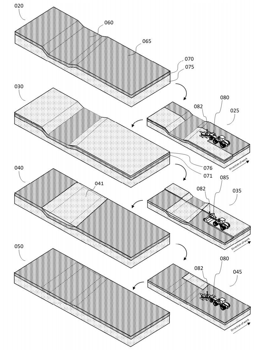
Figure 0 illustrates progressive altering a field's terrain using an embodiment of the invention described herein whereby soil is excavated from certain areas and deposited in another while at the same time the inversion of soil layers preserves the topsoil integrity of the field.
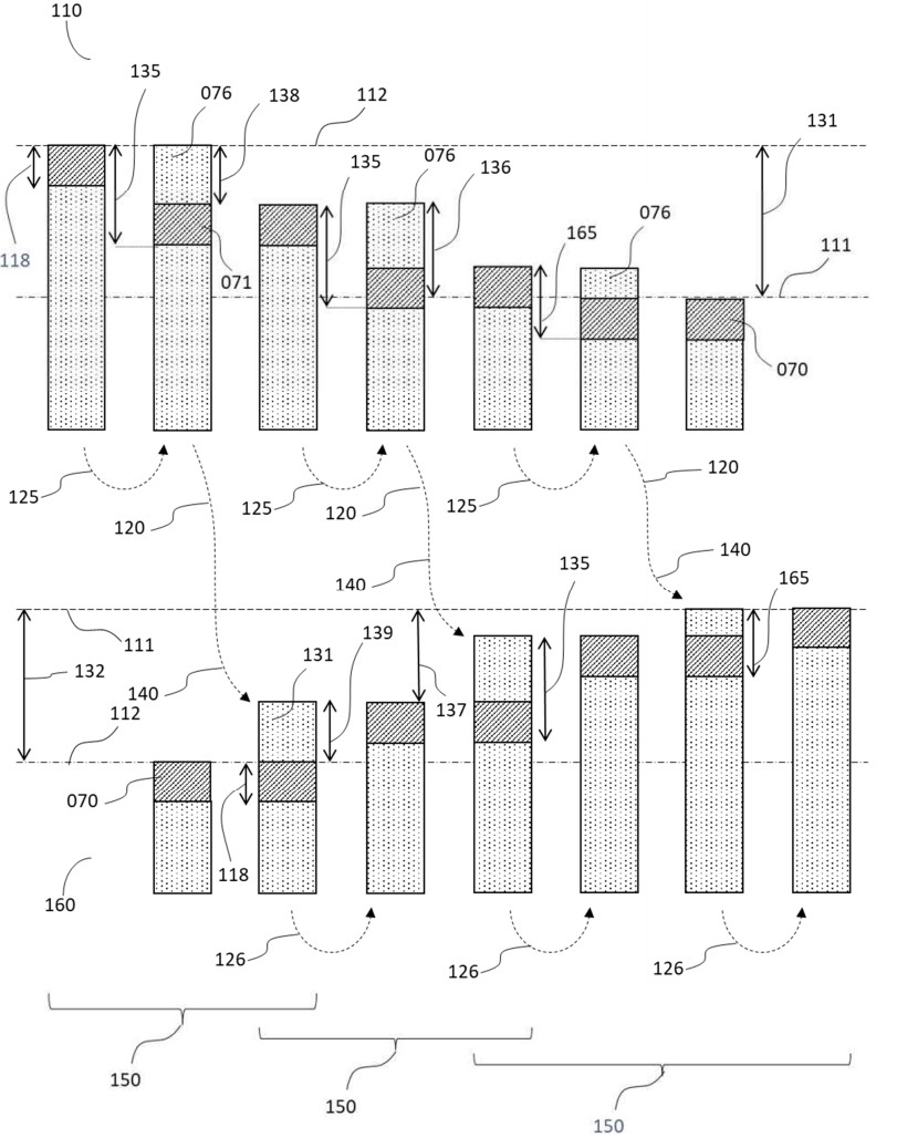
Figure 1 is a left to right sequence of a soil profile from areas of both of excavation (110) and deposition (160), illustrating the progressive effect of a series of soil inversion and surface modification iterations on the soil surface elevation, and its vertical profile.

Figure 2 is a flowchart showing the order of operations and calculations for an embodiment of the method for mechanically excavating soil from a field or field region without removing the topmost layer.
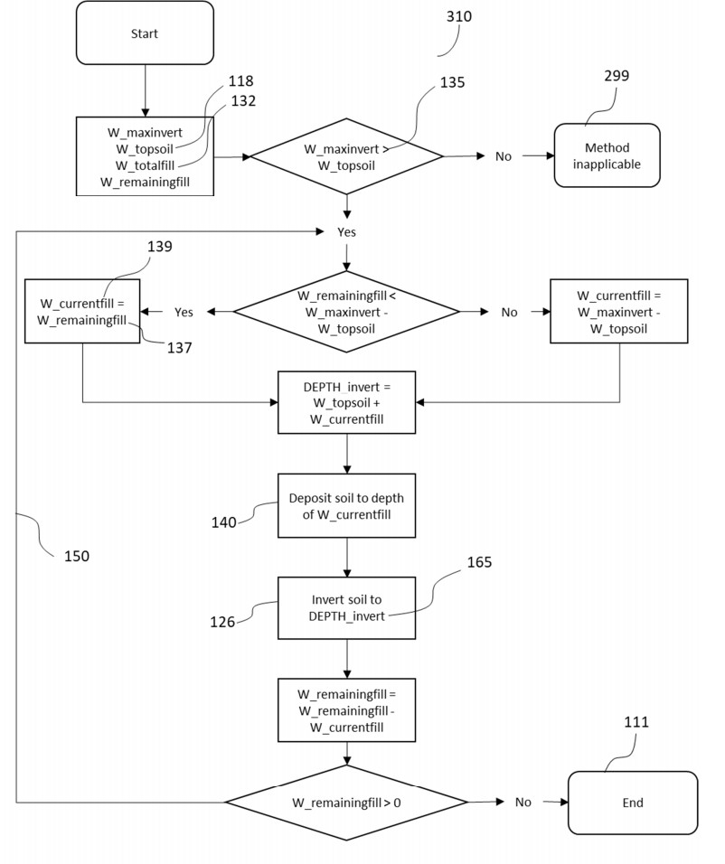
Figure 3 is a flowchart showing the order of operations and calculations for an embodiment of the method for mechanically depositing soil onto a field or field region without permanently burying the topmost layer.
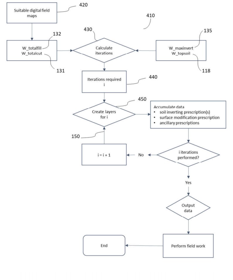
Figure 4 is a flowchart showing one embodiment of the method for creating a set of sequential plans of soil inversion and surface modification operations suitable for use by machine operators.
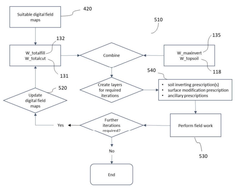
Figure 5 is a flowchart showing another embodiment of the method for creating a set of sequential plans of soil inversion and surface modification operations suitable for use by machine operators.
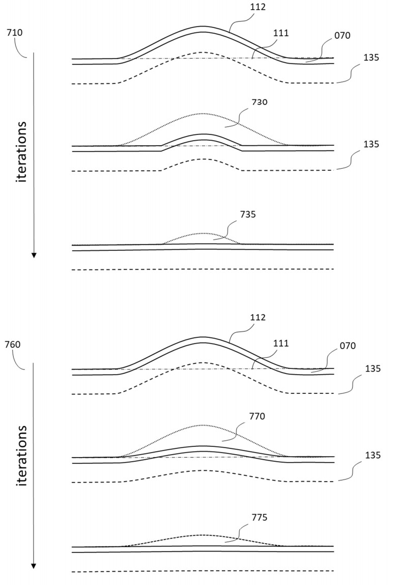
Figure 6 shows two different progressions, each consisting of two iterations, whereby the same mounded surface is flattened using the method of the invention, but where the amounts of soil excavated in each iteration differ.